Filament detection switch is not pressed что значит
Filament sensor problem
Hello everybody,
My JG Aurora A5 was bought Oct 2018.
After several prints and approx 1.5 kg of filament I had problems with interruptions of prints, beeping and finally my A5 was not able to print as there were no files found on the USB. That led me to Da Hai’s video and I tried to reverse the filament sensor plug as instructed. While removing unfortunately I destroyed the mks tft board as glue was not removed completely and so I pulled off the board pin connector including parts of board solder. No chance to repair.
I ordered a new board of which I received version 4.0 instead of 3.0. This was installed and printing is fine without the filament sensor plugged in. Unfortunately this function is lost at the moment.
If I connect filament sensor in any af the directions I receive the message «filament detection sensor is no pressed» when I start printing, independent of filament in or out.
Only exception: if plug put in original orientation (red wire in upper and black in middle) and no filament loaded, there is no message and printer would start.
I tried a new 3 pin filament sensor and same problems. When there is no filament in it starts printing, when feeding filament in it stops
Has anybody made similar experience? Any idea what will help. I also tried what AETEK proposed in the «how filament sensor works» post (install resistor between the outer 2 pins) but nothing changed.
Is there any experience with the version 4.0 tft board? This has little different layout and I am not sure whether I have problem with my sensor or wiring or whether the board needs different wiring.
Обзор PAT9125 оптического датчика филамента для 3d печати
Добрый день друзья. Сегодня я хотел бы рассказать вам про датчик филамента PAT9125, а также про мой опыт общения с ним.
PAT9125 это оптический датчик который применяется на 3d принтерах Prusa. Этот датчик может отслеживать не только момент окончания филамента но и момент его застревания. Например если у вас возникла тепловая пробка.
Главная проблема датчика, его нельзя подключить напрямую к плате с Marlin. Поскольку Marlin поддерживает только подключение энкодера, а этот датчик должен быть подключен по интерфейсу I2C. Чтобы разрешить эту проблему я использовал attiny85 digispark. Датчик подключается к Attiny а уже Attiny в свою очередь эмулирует работу энкодера.
Настройка Marlin
Кроме того нужно раскомментировать параметр #define FILAMENT_RUNOUT_DISTANCE_MM это скажет Marlin что у нас не концевой выключатель, а энкодер. Значение параметра надо уменьшить по умолчанию там стоит 25мм. Чтоб вы понимали сколько это, принтер успеет уложить два слоя калибровочного куба воздухом прежде чем заметит что что-то не так. Я поставил там 5мм можно и меньше но тогда можно столкнутся с ложными срабатываниями.
В файле Configuration_adv.h нужно раскомментировать #define ADVANCED_PAUSE_FEATURE
В файле Pinout вашей платы надо задать пин к которому будет подключен датчик в параметре #define FIL_RUNOUT_PIN.
Особенности работы датчика
Во первых я очень надеялся что поскольку я использую прозрачную трубку для филамента то датчик можно будет одеть прямо на неё и он будет видеть только филамент. Но оказалось, что датчик прекрасно видит эту прозрачную трубку и мне пришлось делать в ней окно.
Следующая особенность касалась уже Attiny. Сначала я подключил принтер к пину P3 и Attiny просто не стала запускаться. То есть без подключения к принтеру все прекрасно работает, а стоит подключить Attiny не стартует. После этого я подключил принтер к пину P5, Attiny загрузилась но порт просто не работал на нем всегда был высокий потенциал, возможно у меня оказалась бракованная Attiny. Все заработало только когда я подключил принтер к пину P1, пин на котором располагается диод.
Также я хочу отметить что датчик отслеживает отдельно движение по оси X и по оси Y. В моем случае используется ось X, но если вы захотите расположить датчик по другому. Например расположить его перпендикулярно движению филамента, то надо в прошивке Attiny заменить ось X на Y.
BigTreeTech Smart Filament Detection Module not triggering on when connected to PT-DET #144
Comments
TerawattX commented Dec 5, 2019
I have configured by board and connected the Smart Filament Detection Module per the provided instructions in the Github repository, however as soon as the first layer has started it will indicate there is no filament in the machine and launch the M600 command.
This issue was also reported by another user on the Filament Detection Module repo:(bigtreetech/smart-filament-detection-module#1)
They were able to confirm signaling from the module, but the board was not sensing it.
The text was updated successfully, but these errors were encountered:
pa0los commented Dec 6, 2019
PT-DET is meant for switching the power supply.
For filament runout you should use E0-STOP connector (see the pin defines file in Marlin for SKR mini E3).
TerawattX commented Dec 6, 2019
That certainly explains the issue, though I could have sworn I read you could change the pins in the config to use PC12 vs PC15.
Question: The detection module ships with a 3 to 4 pin cable, E0-Stop is a 2 pin connector. Will the Filament Detection module still operate properly on 2 pins vs 3? I know this is a different product from the SKR board, but since both are BigTreeTech products I figured it wouldn’t hurt to ask.
TerawattX commented Dec 20, 2019
So I’m going to reopen this because the documentation isn’t very clear on the issue. The PDF for the module simply states to use «any extended interface.» I took this to indicate that PT-DET would work as long as you set the interface accordingly in the pins_BTT_SKR_MINI_E3.h file.
There is also a comment by another user that they were able to get theirs working on PT-DET by setting FIL_RUNOUT_INVERTING to true, however when I do this it simply is always open and never triggers when it runs out of filament.
Is there a clearly defined list of which interfaces are valid? As I stated earlier, I don’t think E0-Stop would work because the module requires a SIN, VDD, and GND wire, and I’d use the Servos interface, but that’s where my BLTouch is hooked up. Any alternatives or confirmation one way or another about PT-DET?
SCR1.4/Marlin2.0/Ender 3PRO проблема с датчиком окончания нити.
Статья относится к принтерам:
Всем доброе время суток столкнулся с проблемой работы датчика обрыва филамента. Проблема заключается в постоянном диалоге о замене нити
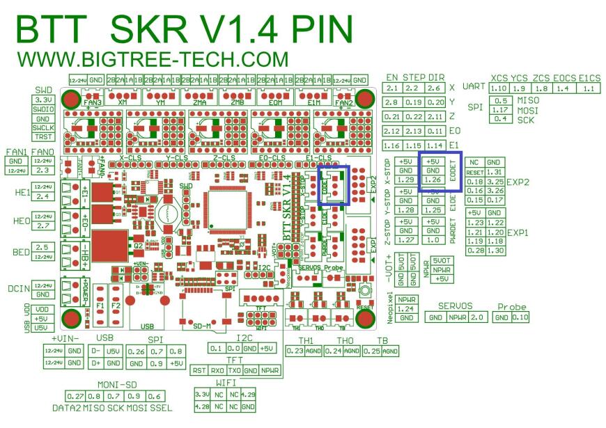
#define FIL_RUNOUT_PIN P1_26 // E0DET
#define FIL_RUNOUT2_PIN P1_25 // E1DET
#define NUM_RUNOUT_SENSORS 1 // Number of sensors, up to one per extruder. Define a FIL_RUNOUT#_PIN for each.
#define FIL_RUNOUT_STATE HIGH // Pin state indicating that filament is NOT present.
#define FIL_RUNOUT_PULLUP // Use internal pullup for filament runout pins.
//#define FIL_RUNOUT_PULLDOWN // Use internal pulldown for filament runout pins.
// Set one or more commands to execute on filament runout.
// (After ‘M412 H’ Marlin will ask the host to handle the process.)
#define FILAMENT_RUNOUT_SCRIPT «M600»
// After a runout is detected, continue printing this length of filament
// before executing the runout script. Useful for a sensor at the end of
// a feed tube. Requires 4 bytes SRAM per sensor, plus 4 bytes overhead.
#define FILAMENT_RUNOUT_DISTANCE_MM 7
// Enable this option to use an encoder disc that toggles the runout pin
// as the filament moves. (Be sure to set FILAMENT_RUNOUT_DISTANCE_MM
Adding filament sensor in SKR electronics (MINI E3, v1.3, v1.4 and v1.4 Turbo)
STL format is dead, is it?
Currently, the vast majority of 3D printer manufacturers offer us the filament detection function (or lack of it, to be more precise) as something common.
This means that when our spool of filament runs out, Marlin automatically stops the current job and offers us the ability to insert another spool without losing our current impression.
And although most printers already come with this sensor as standard, it is likely that if you bought yours a few years ago you will not have this interesting functionality. Anyway, this should not worry you, installing a sensor is reduced to modifying a few lines of Marlin code and adding a mechanical (or optical) limit switch.
In today’s article we will address this issue, and you will see that adding it to your printer is not at all complicated. And remember, you can find us daily on our Telegram channel or on our social networks (Facebook , Twitter, Instagram), where you can join our community of 3D printing fanatics.
Brief introduction
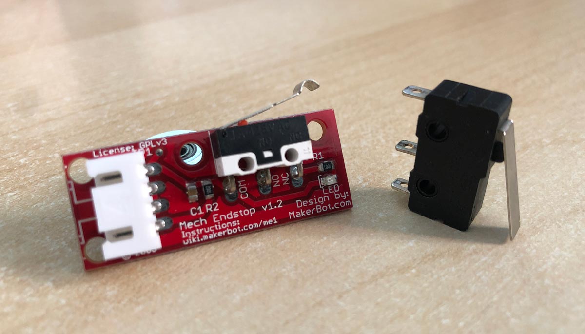
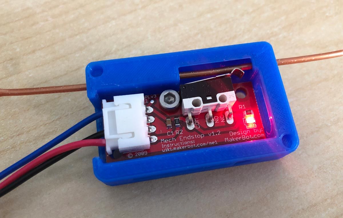
A filament sensor is a simple limit switch (endstop) whose function is simply to detect the possible absence of filament during our impressions. These are usually optical or mechanical.
I use a fairly common and inexpensive mechanical one in my printer. Actually it is not important, both will work without any problem, so the choice of it is in your hands.
There are also cut sensors that various manufacturers sell encapsulated and ready to plug. It is certainly the most comfortable, but sometimes the prices are excessively high.
Finally, note that I am using SKR v1.4 Turbo electronics, together with a TFT35 V3.0 Hybrid display. While the Marlin modifications will be for this board, I will add the variations for the other SKR electronics currently available on the market.
In any case, the Runout Sensor functionality (filament detection) is common to Marlin, so regardless of the electronics or display you use, the changes to be made here, except the pins where we will connect the limit switch, are common.
Required components
It doesn’t make much sense to buy a sensor for 15 euros when you can simply make one with a limit switch that costs just 1-2 euros.
However I leave you here some links where you can buy the one I use in my printer, as well as some commercials that exist in the market ready to connect.
As you may know beforehand, these links are affiliate links, which means that 3DWork will receive a small commission from the sale, and you will be supporting my website.
Endstop connection to electronics
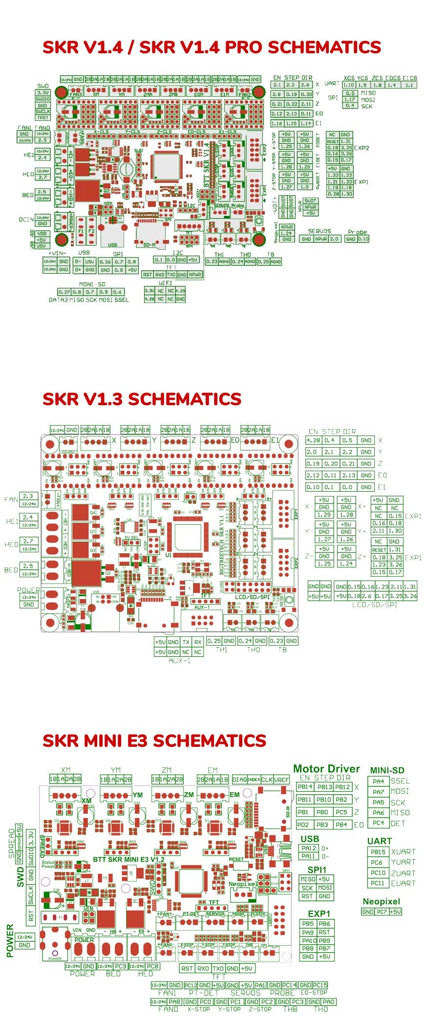
The connection of the sensor to our board will depend on what type of electronics we have. Below I leave you the default pins that we must use, as well as an image with the diagrams that will help you locate the connectors and the different pinouts on the board.
However, for reference, the pin configuration is in your electronics file, in the \Marlin\src\pins folder. Then, you must go to the folder that corresponds to the microprocessor of your board and select the file.
It goes without saying that if you wish, you can change the assignment pins and use another free connector for this function. This way if you have a damaged entry you can move to another with great ease, since Marlin is quite “friendly” in this regard.
It is very important to check the pinout before connecting the sensor to your electronics, otherwise if you make a mistake you could damage it. In my case, my limit switch already came with a 3-wire cable correctly configured and with the possibility of inserting it only in the correct position.
But there are simply 2-wire limit switches, which you must connect to the pins corresponding to C or COM (signal) and GND (ground) in your electronics. Ideally, connect C to the signal pin and NC to ground as it is less prone to possible “noise”. In this way, if the cable were damaged for any reason, it would give the same signal as if you had pressed the limit switch, protecting that the limits of the printer are not exceeded in any case (or in breakage).
Also, some limit switches require removing the PULLUP from the Marlin configuration to operate correctly. If this is your case, you must edit this line and delete the comments:
Location of files and schemas
| Electronic board | Files | Pinouts |
| SKR v1.4 Turbo | lpc1768\pins_BTT_SKR_V1_4.h | FIL_RUNOUT_PIN P1_26 (E0DET) FIL_RUNOUT_PIN2 P1_25 (E1DET) |
| SKR v1.4 | lpc1768\pins_BTT_SKR_V1_4.h | FIL_RUNOUT_PIN P1_26 (E0DET) FIL_RUNOUT_PIN2 P1_25 (E1DET) |
| SKR v1.3 | lpc1768\pins_BTT_SKR_V1_3.h | FIL_RUNOUT_PIN P1_28 |
| SKR Mini E3 v1.0 | stm32f1\pins_BTT_SKR_MINI_E3_V1_0.h | FIL_RUNOUT_PIN PC15 (E0-STOP) |
| SKR Mini E3 v1.2 | stm32f1\pins_BTT_SKR_MINI_E3_V1_2.h | FIL_RUNOUT_PIN PC15 (E0-STOP) |
| SKR Mini E3 v2.0 | stm32f1\pins_BTT_SKR_MINI_E3_V2_0.h | FIL_RUNOUT_PIN PC15 (E0-STOP) |
The location of the connectors on the different electronic boards can be found in the following official SKR diagrams. You can click on the image to enlarge it.
Setting up Marlin for our endstop
The configuration could not be simpler, it is simply to modify a few lines of code and we will have the menu available on our display and the autodetection active at all times.
I know modifying Marlin may seem complicated, but nothing could be further from the truth. In the event that you have never modified the firmware, I would recommend that you take a look at a very interesting article that I wrote some time ago.
In it you will find all the necessary information to be able to modify it at will, compile it and upload it to your electronics. You can visit it at the link Complete guide: Configure Marlin 2.0.x from scratch and not die trying
And as a complementary article, in order to use Visual Studio Code and compile 32-bit firmwares, this other must-read article Configure and update your 3D printer using Visual Studio Code and Platform.io
Configuration.h fil
The first thing we are going to do is activate the main function of filament detection. We will edit the Configuration.h file and look for the FILAMENT_RUNOUT_SENSOR function.
By default in Marlin it is deactivated, so we will activate it by eliminating the two characters in front of it “//”. It should look something like this:
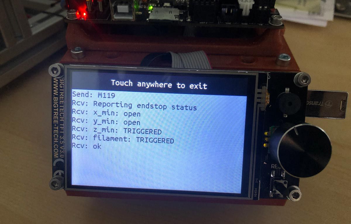
Activating this option, we will have the menu available. Now we must check that indeed the sensor is acting as it should. To do this we will execute the gcode M119 command, which will indicate the status of the sensor at all times.
In my case and as I have a hybrid TFT35 BTT display, I can execute gcode commands directly from the screen, something really practical and that saves you time for these tasks.
When executing it and having the sensor correctly configured, the following information appears on the screen:
As you can see in the image above, there are two states for the limit switches. OPEN (not pressed) and TRIGGERED (pressed). When the filament is inserted, the sensor must be in the TRIGGERED state since it obviously squeezes the lever.
If not, and it will indicate the OPEN status, you will have to change its logic. To reverse the logic, we will edit a line in the Marlin code, which depending on the Marlin version will be different, so I put the two variants:
Marlin v2.0.6.x or higher
In these firmware versions you must change the state by modifying the word that follows the FIL_RUNOUT_STATE constant, which will be HIGH or LOW. By default Marlin is configured as LOW, so if you need to invert the logic, change it to HIGH.
Marlin lower than v2.0.6.x
In lower versions it is similar, it looks for the constant FIL_RUNOUT_INVERTING and changes the value FALSE to the value TRUE, as simple as that.
And finally, in the Configuration.h file, we will activate the NOZZLE_PARK_FEATURE option. We proceed to uncomment the constant so that it looks like this:
Configuration_adv.h file
Now it’s the turn of the Configuration_adv.h file, which also requires a very simple last change.
This will activate the advanced printing pause, which includes different functions such as filament loading speed, extraction, purging and many other things.
For this purpose we are going to uncomment the following line:
Final notes
As you have seen, the process of configuring a filament sensor does not present any difficulties. And if you have followed the instructions you should already have the filament sensor active and functional.
Although it does detect the filament cut and tells us to press OK to continue again, when you try it does not respond and remains completely hung. We will wait to see if BigTreeTech can solve this problem in future reviews of the display (or some alternative configuration appears that I am currently unaware of).
Without further ado I say goodbye as always. I hope you find this short useful article useful and I hope to see you soon on our Telegram channel.


