Double balanced mixer что это
Double Balanced Mixer Theory
The double balanced mixer is a diode bridge mixer that uses two single-ended to differential transformers, or baluns, to create the multiplication of two input frequencies and cancel many of the unwanted harmonics and signals. Most notably is the cancelation (ideally) of the local oscillator and the input at several harmonics.
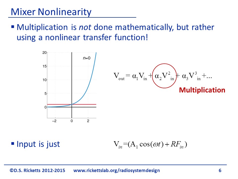
Mixers are simply multipliers of voltages and/or currents. While we may mathematically thing of them as multipliers, there is no circuit element that directly “multiplies” signals. To achieve multiplication, we use a nonlinear element that has a strong second order term in its Taylor series. Other terms from the Taylor series could be used but generally the amplitude of the coefficients are small. The input is generally the sum of the local oscillator (LO) and intermediate frequency (IF) for an up converting mixer, or an LO and RF signal for a down converting mixer.
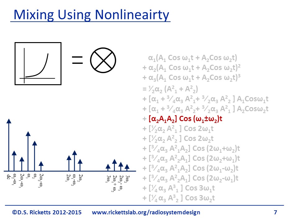
In this example, two inputs, A1 and A2, are inserted into a Taylor series. Many terms are created. We focus on the one in red, as it will have the strongest contribution since 2 is larger than higher order coefficients. Important in this derivation is that there are many harmonics generated by using this nonlinearity to perform multiplication. Eliminating or compensating for these harmonics will be one of the main challenges in designing a diode mixer.
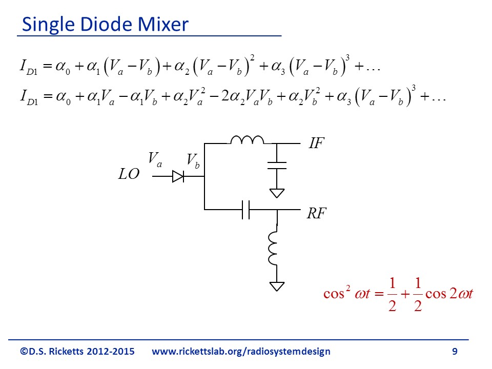
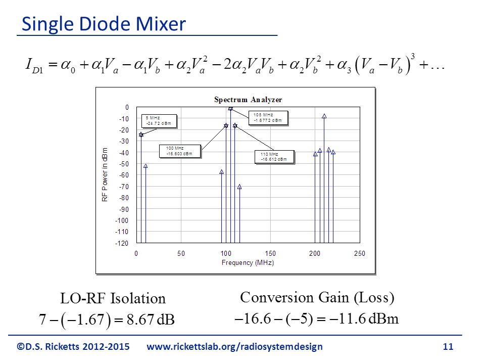
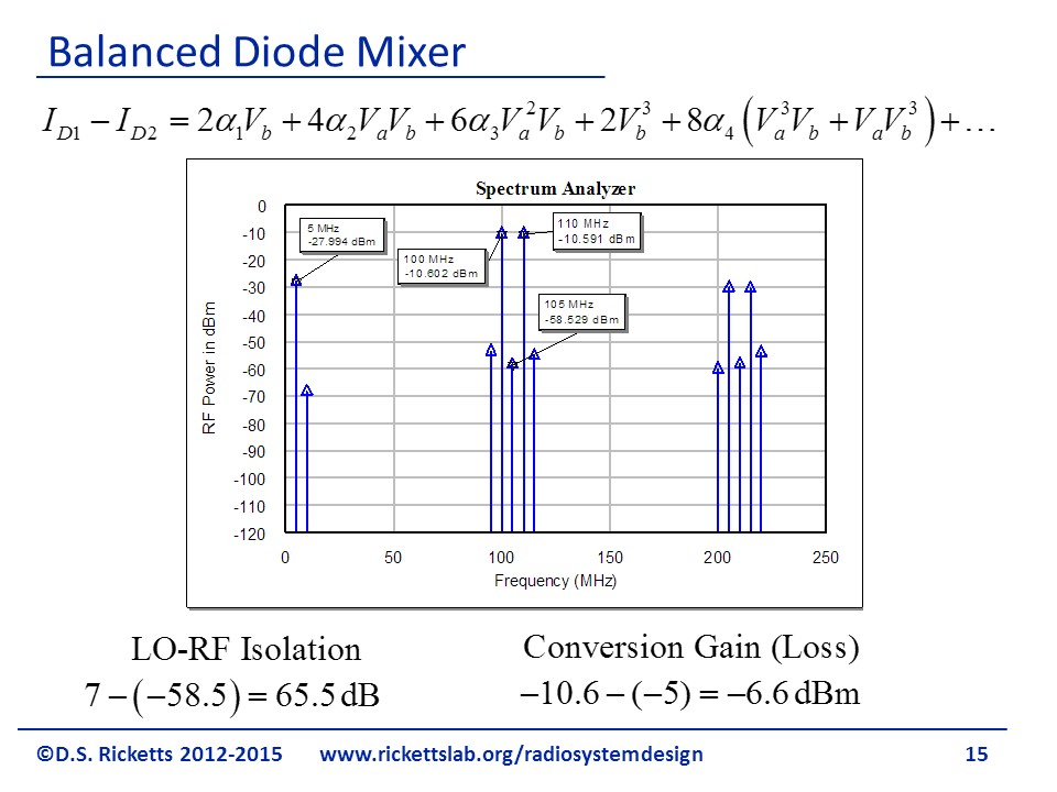
To illustrate, we look at a simple diode and examine the current through it, resulting from the voltage across the device. The voltage is due to the LO and either the IF or RF (either could be the stimulus). Let us assume we have an IF of 5 Mhz and an LO of 105 MHz and the RF port is the output (an upconverting mixer). The series expansion (assuming 0=0) gives us current at the following frequencies: the LO (term 2), the IF (term 3), a dc component and one at twice the LO – see identity in figure (term 4), the desired RF at LO±IF (term 5), a dc component and one at twice the IF (term 6) and then term 7 provides several harmonics and a signal at our LO±IF, which arises since due to a term when one expands term 7 and uses the identity in red. This term is expected to be very small due to 3. The main takeaway – we achieved our signal multiplication, but with it also have many harmonics.
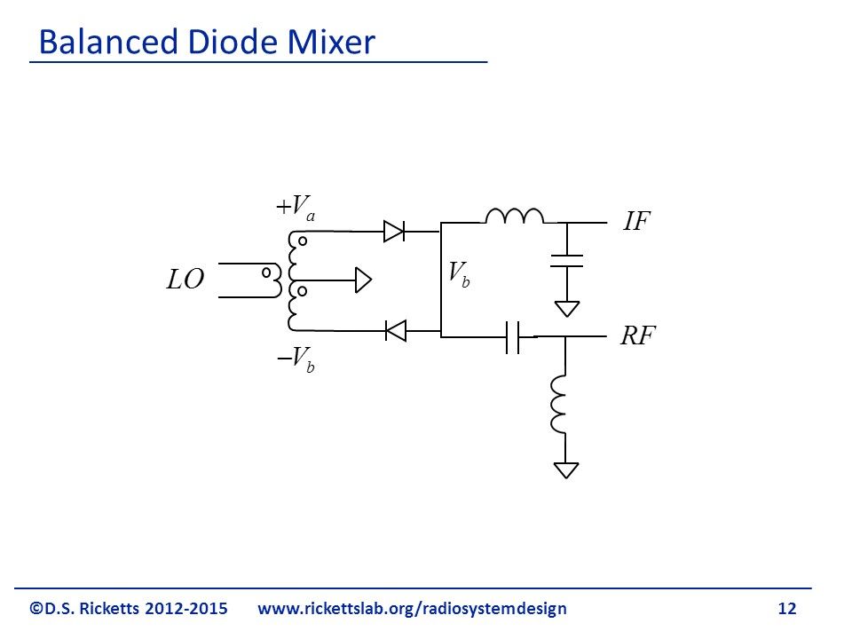
The simple LC filter separate the low frequency from the high frequency through the IF and RF ports.
The balanced mixer uses two diodes, in opposite polarities, to cancel the LO component. The transformer in the picture is a balun, and simple converts the LO from single ended to differential.
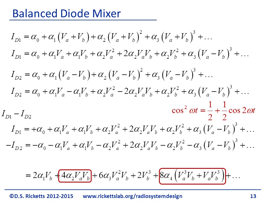
The mathematics for calculating the difference in diode currents is detailed, but straight forward. Looking at the lower portion, we can see that we have achieved our desired multiplication. In addition we can see that Va and (Va) 2 has disappeared through simple cancelation.
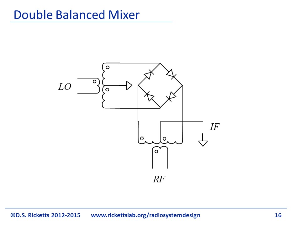
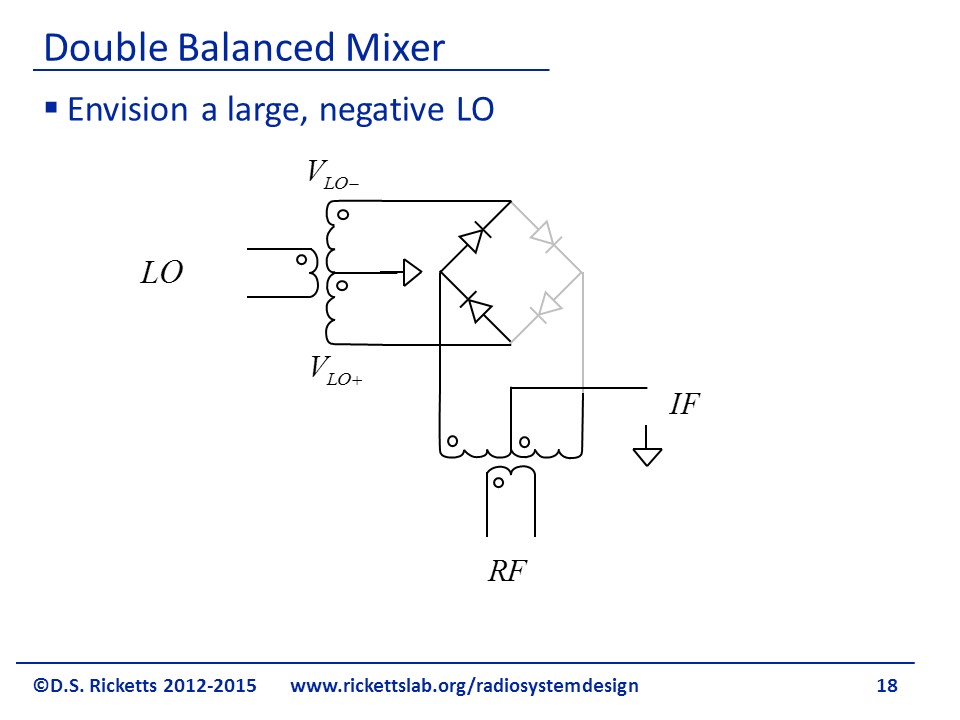
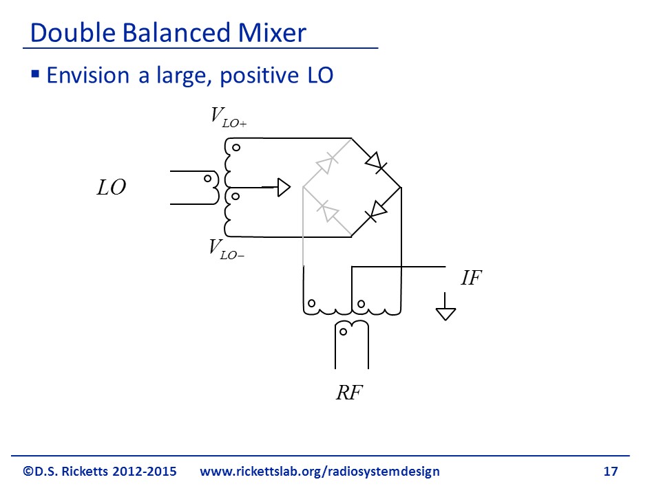
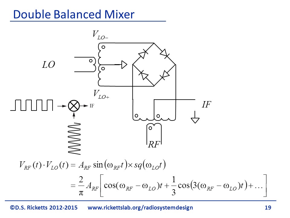
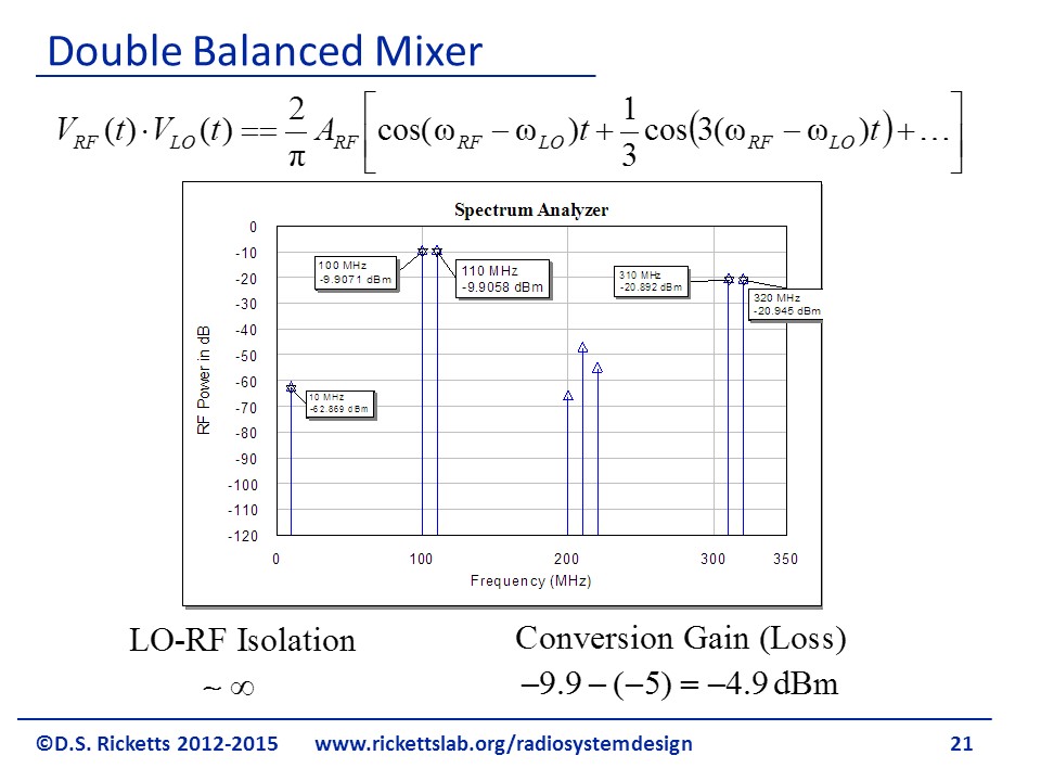
The double balanced mixer provides similar IF cancellation as did the balanced mixer for LO. Instead of the detailed mathematical analysis, we can look at the operation for a large LO and treat the diodes as switches. When they are forward biased, the signal passes through them. When they are reversed biased, they are off. This way of thinking works only if the LO is much larger than a diode forward bias voltage.
With the LO in the polarity shown, the left two diodes are on. We will consider an upconverting mixer as it is a little easier to explain, but the mixer works both as an upconverting and down converting.
On the other half of the LO cycle, the right two diodes are on and provide a ground for the non-dot side of the RF balun. The RF is then seen at the IF port without a polarity change.
Double Balanced Mixer: circuit, theory, operation
Double balanced RF or frequency mixers are able to provide high levels of performance and they are used in many exacting RF applications.
Double balanced mixers are able to provide very high levels of performance in RF or frequency mixing applications.
The action of the double balanced mixer means that the input RF and local oscillator signals are “balanced out” and their level is considerably reduced at the output by having differential circuits on their inputs.
This reduces the need to remove the often unwanted RF and local oscillator signals at the output and reduces the effect of these input signals causing intermodulation distortion.
In view of the level of their usage, double balanced mixers are widely available from a number of specialist RF component suppliers. These suppliers have a wide range of double balanced mixers both as hybrid diode and FET based mixers as well as fully integrated MMIC based devices that should meet the requirements for the majority of RF circuit design applications.
Need for balanced mixers
Many forms of mixer are not balanced and as a result they allow through considerable levels of the local oscillator and RF signals. These are normally not wanted and normally they would have to be removed by filtering which is often inconvenient and expensive. The solution is to balance the mixer to remove the input signals.
There are two types of RF mixer that are balanced:
While single balanced mixers offer many advantages over simpler designs, the double balanced mixer is more widely used. However there are a number of advantages and disadvantages over a single balanced mixer to consider:
Double balanced mixer advantages.
Double balanced mixer disadvantages.
Despite the increased complexity, double balanced mixers are more widely used for applications where high performance is paramount.
RF / frequency mixer ports
Like all other RF mixers, double balanced mixers have the same three ports or connections.
Types of double balanced mixer
Double balanced mixers come in a variety of forms using different types of electronic component and having some slightly different formats.
Hybrid based diode double balanced mixer: This type of double balanced mixer is the stereotypes double balanced mixer. It uses two main electronic components namely a ring of four diodes, which are normally Schottky diodes and baluns on two or more ports. It is primarily these baluns that add the cost and also limit the frequency response of the RF mixer.
Hybrid based active double balanced mixer: This form of double balanced mixer replaces the diodes with an active device to act as the switching elements within the ring circuit. Again hybrid baluns are used on both input circuits, but the format is again the same. The electronic components include the expensive wound baluns as well as the active devices, e.g. FETs which have a good switching performance.
Active double balanced mixer: Using active differential amplifier circuits, it is possible to achieve the balanced operation for the RF mixer. This enables the complete mixer circuit to be fabricated on a single semiconductor chip. Most high performance RF mixers, as well as many lower performance ones use this technology. The cost of the high performance active double balanced mixers is much less than those using wound components, and they offer a much wider bandwidth.
In view of the better RF performance and lower cost of active double balanced mixers using no hybrids, this type of mixer is used in most RF circuit design applications these days. Mixers are available in standard surface mount technology packages for many applications and for more exacting ones, special monolithic microwave ICs, MMICs are available for RF mixers.
Reversing switch mixers
Double balanced mixer basics
The most common form of double balanced mixer is the diode double balanced mixer. In its simplest form it consists of two unbalanced to balanced transformers and a diode ring consisting of four diodes as shown.

Although the design of the RF mixer looks straightforward, high performance mixers are designed and built to exacting standards to achieve the high levels of performance needed.
One of the key specifications for a double balanced mixer is whether any of the LO or RF signals appear at the IF port. This depends upon the diode and transformer uniformity. In addition to this the circuit offers high isolation between the RF and IF ports because the balanced diode switching precludes direct connection between T1 and T2.
Double balanced mixer components
Although there are comparatively few components in a double balanced mixer, their individual performance is crucial to the performance of the RF mixer as a whole.
Normally Schottky barrier diodes are used for the diode ring. They offer a low on resistance and they also have a good high frequency response. Ordinary signal diodes may be used for low performance applications, although the cost difference is small. It is found that the diode forward voltage drop for the diodes determines the optimum local oscillator drive level. RF mixers requiring to handle a high RF input level will need a correspondingly high LO input level. As a rule of thumb the LO signal level should be a minimum of 20dB higher than either the RF or IF signals. This ensures that the LO signal rather than the RF or IF signals switch the RF mixer, and this is a key element in reducing intermodulation distortion, IMD, and also maximising the dynamic range.
To increase the required drive level, it is possible to place multiple diodes in each leg. The most common LO drive level for a double balanced mixer is probably +7dBm. However they can be obtained with a variety of drive levels. Values of 0, +3, +7, +10, +13, +17, +23, and +27 dBm are normally available.
In order to provide the required level of performance, the quad diodes used win these mixers are generally fabricated monolithically. By doing this they will have very closely matched performance parameters, and in particular the level of forward voltage will be virtually identical in all the diodes.
The transformers are also critical to the performance of the RF mixer. Creating a wideband balun for the mixer is one of the key elements within the overall mixer design and achieving the required bandwidth and performance can be difficult to achieve.
The matching of the transformers and the individual legs are important in determining the balance of the RF mixer. The transformer also plays an important role in determining the conversion loss and drive level of the RF mixer. As the transformers are wound on a ferrite core, the core loss, copper loss and impedance mismatch all contribute to the transformer losses.
Double balanced mixer operation
The operation of the double balanced mixer is relatively easy to understand. The local oscillator, LO, signal turns on first one arm (D3, D4), and then the other (D1, D2) within the diode ring.
As the points where the LO signal enters the diode ring at the junction of D1 and D4 appear as a virtual earth to the RF signal, this means that the points where the RF signal enters are alternatively connected to ground as the diodes turn on and off.
Double balanced FET mixer
While diode mixers are able to offer excellent performance, the increase in use of wireless and general radio communications systems means that receivers need to be able to accommodate a larger number of local strong signals than may have been the case previously. Better low end noise performance along with higher third order intercept points are required. The performance figures required by double balanced diode mixers cannot always meet the requirements for some designs, unless significant tailoring is undertaken and this increases the costs beyond economic viability. Conventional double balanced diode mixers can offer a third order intercept performance up to figures of between about +25 and +30 dBm.
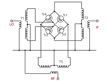
The diagram shows the basic concept of a double balanced FET mixer. However some mixers require the application of a DC bias to ensure the correct switching of the diodes, and some mixers show a high conversion loss or noise figure. Double balanced FET mixers using discrete components can sometimes be optimised to provide better performance figures, and newer commercially available items are also offering better performance.
Practical aspects for double balanced mixers
Using double balanced mixers enables very high levels of performance to be achieved. However a few useful hints and tips ensure that the mots can be made from using them.
Double balanced mixers are widely used in RF applications where performance is paramount. Although they are more costly than many other forms of frequency mixer, they offer the performance that is often required Typically these mixers are bought from specialist manufacturers because they have the expertise and the manufacturing capability for the transformers and other components that are required. Additionally the development and optimisation cost is spread over a large number of units.
RF Wireless World
Home of RF and Wireless Vendors and Resources
One Stop For Your RF and Wireless Need
RF Single balanced mixer vs double balanced mixer vs triple balanced mixer | difference between Single balanced mixer, double balanced mixer and triple balanced mixer
This page compares RF Single balanced mixer(SBM) vs double balanced mixer(DBM) vs triple balanced mixer and mention difference between Single balanced mixer and double balanced mixer type. It also compares these two types with doubly double balanced mixer i.e. triple balanced mixer.
There are two main types of RF mixers viz. passive mixer and active mixer. Passive mixers are made of using diode devices. Active mixers are made of using BJTs or FETs. Refer RF Mixer basics which describes circuit symbol of RF mixer, operation of RF mixer using mathematical equation and rules of thumb to be considered while using mixer in RF design.
RF Mixers are widely used in RF and Microwave circuit design mainly RF up conversion and down conversion. The RF device which does this is referred as RF Transceiver. Refer Design of RF frequency converter using discrete RF mixers. RF Mixers are available as connectorized modules as well as in the form of drop-in modules.
Single device mixer or unbalanced mixer
Figure-1 depicts single device mixer type. It uses one nonlinear diode device. To achieve best performance i.e. to obtain maximum conversion gain, LO node should be SC(short circuit) at RF and IF frequencies. RF node should be SC at the LO frequency in order to prevent LO leakage into RF port.
Advantage: It is extremely useful for very high frequency in the millimeter wave frequency band. It is very simple in design and can help achieve broad bandwidth.
Disadvantage: It does not attenuate LO AM noise and needs injection filter.
As mentioned unbalanced mixers allow unwanted considerable levels of LO and RF signals. Expensive filters are needed to remove these. Moreover it is inconvenient to employ these filters in the design. In order to avoid these disadvantages of unbalanced type of mixers, balanced type of RF mixers have been designed and developed.
Following are the benefits of balanced RF mixer type over unbalanced single device mixer type:
• Rejection of spurious responses and intermodulation products.
• Better LO-to-RF, RF-to-IF, and LO-to-IF isolation.
• Rejection of AM noise in the LO as mentioned above.
The demerits of balanced mixers are their requirement of greater LO power. Moreover they are complex in design compare to single device type.
There are three types of balanced RF mixers i.e. single balanced, double balanced and triple balanced (Doubly double balanced). Let us compare and differentiate these RF mixer types with respect to their merits (advantages) and demerits(disadvantages).
Single Balanced Mixer
Figure-2 depicts Single Balanced Mixer type. It provides isolation between LO and RF inputs to solve the issues faced by single device mixer type. It uses two diode devices. It can be realized using two single device mixer types connected via 90 degree hybrid or 180 degree hybrid circuit.
Double Balanced Mixer
Figure-3 depicts Double Balanced Mixer type. As shown it will have 4 diodes arranged in ring. It will demonstrate same effect as 2-diode mixer circuit.
There are two double balanced RF mixers e.g. star mixer and ring mixer.
Doubly Double Balanced Mixer-Triple Balanced Mixer
Following table mentions difference between Single balanced mixer, double balanced mixer and triple balanced mixer types.
Analog Devices Wiki
Table of Contents
Activity: Active Mixers
Objective
The objective of this activity is to understand the basic concept of active mixers.
Background
A mixer is a three-port device that can modulate or demodulate, and which can either be passive or active. The main function of a mixer is to change the frequency of a signal while preserving every other characteristic of the initial signal. What differentiates an active mixer from a passive mixer is that an active mixer employs active devices to apply conversion gain.
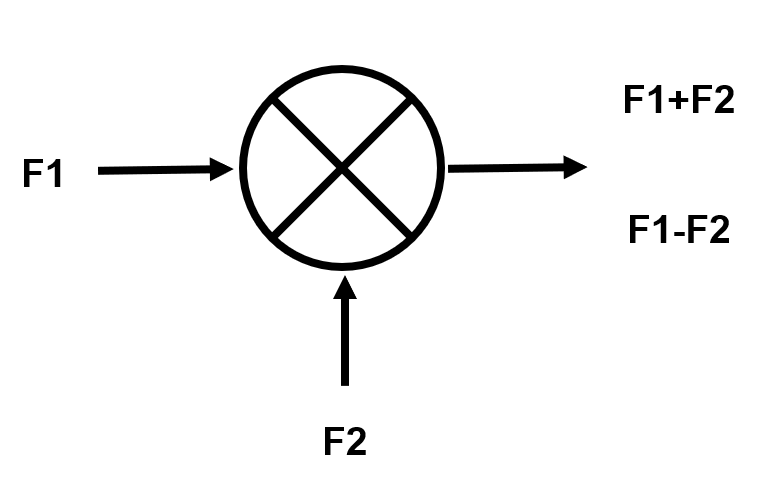
Figure 1. Symbolic Representation of a Mixer
The output of mixer can be of two forms, thus the diagram shown in Figure 1. The mixer accepts two frequency input and delivers one frequency output. The output, as shown in the diagram, can either be the sum or the difference of the two input frequencies. These frequencies can be identified as the following; Local Oscillator (LO), Radio Frequency (RF), and Intermediate Frequency (IF).
Mainly, mixers are used to perform frequency conversions which can be classified as up-conversion and down-conversion. The LO port is always an input port unlike the RF and IF port which can either be an input or output depending on the application. In a down-conversion mixer, the other input port is the RF port and the output is at a lower IF. This is shown in Figure 2a.
Figure 2a. Down-conversion Mixing Representation
In an up-conversion mixer, the other input is the IF and the output is the RF signal. This is shown in Figure 2b.
Figure 2b. Up-conversion Mixing Representation
Materials
ADALM2000 Active Learning Module
Solder-less breadboard, and jumper wire kit
2 1 kΩ resistor
2 6.8k kΩ resistor
1 OP37 precision op-amp
1 LTC1043 precision switched-cap block
3 N-channel MOSFET (2-ZVN3310, 1-ZVN2210A)
Single Balanced Active Mixer
Mixers can also be classified as single balanced mixer and double balanced mixer, each has its own advantages and disadvantages.
A single-balanced mixer often called a balanced mixer, is a type of mixer which suppresses either the LO or RF signal but not both. This configuration is hardly used because of its susceptibility to noise in the input LO signal. The main drawback is its IF-LO feed-through, which means the LO signal can leak into the IF signal if the IF signal frequency is not much lower than the LO signal frequency. Shown in Figure 3 is a simple circuit of a single balanced mixer.
Figure 3. Single Balanced Mixer
Hardware Setup
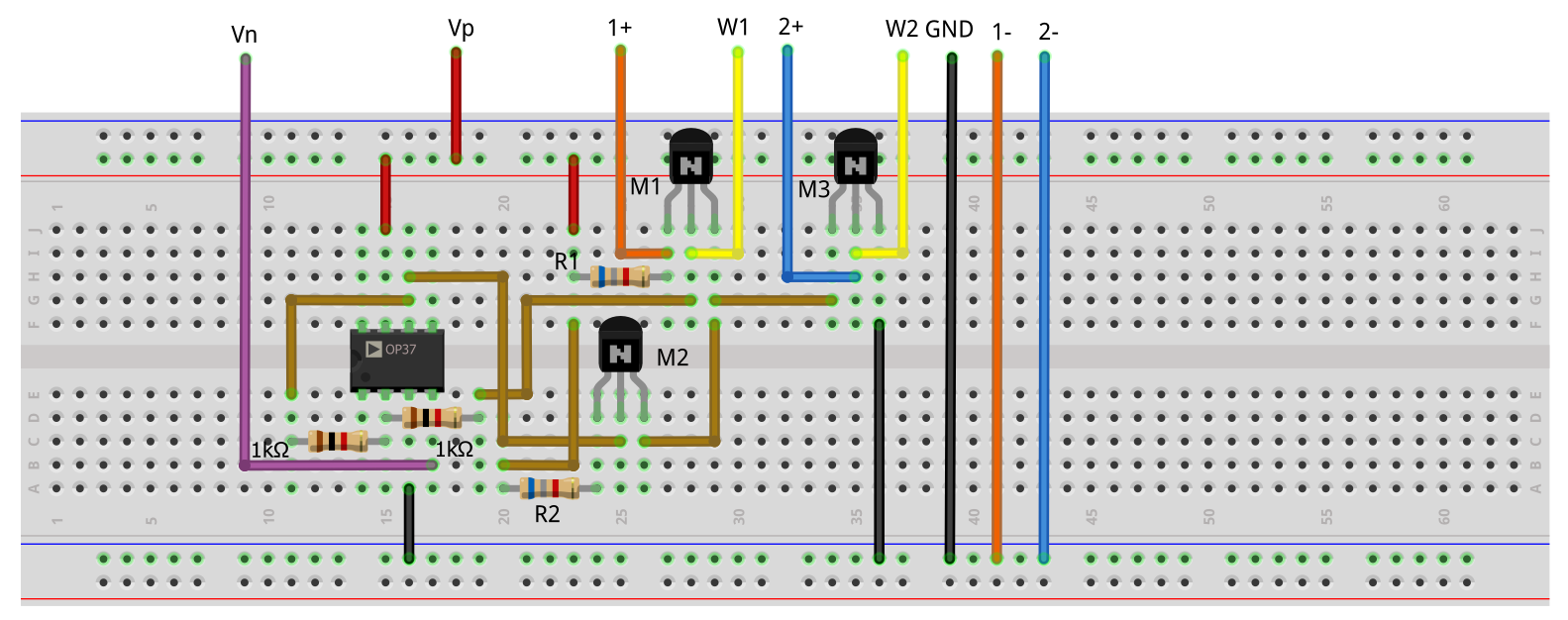
Build the following breadboard connection shown in Figure 4.
Figure 4. Single Balanced Mixer Breadboard Connections
Procedure
Figure 5a. Up-conversion Spectrum Plot
For the Down-conversion mixing, set W2 to 5V, 260kHz sine wave, this will serve as the RF input to the mixer. So, our expected output is at 50kHz and spectrum result should be like Figure 5b.
Figure 5b. Down-conversion Spectrum Plot
Single balanced active mixer implemented with LTC1043
Background
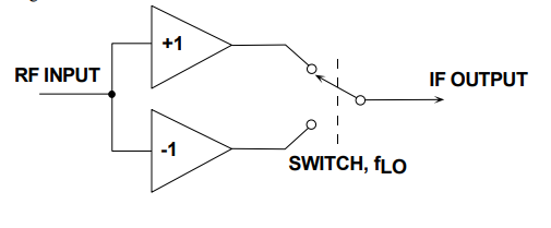
Ideally, to meet the low-noise, high-linearity objectives of a mixer we need some circuit that implements a polarity-switching function in response to the LO input. Thus, the mixer can be reduced to Figure 6, which shows the RF signal being split into in-phase (0°) and anti-phase (180°) components; a changeover switch, driven by the local oscillator (LO) signal, alternately selects the in-phase and antiphase signals. Thus reduced to essentials, the ideal mixer can be modeled as a sign-switcher.
Figure 6. An Ideal Switching Mixer
Simulation
For demonstration of the mixing concept we can use the ideal switching mixer in the Figure 6. The mixer can be built with the LTC1043 CMOS analog switch, which is a monolithic, charge-balanced, dual switched capacitor instrumentation building block. A pair of switches alternately connects an external capacitor to an input voltage and then connects the charged capacitor across an output port. An internal clock is provided and its frequency can be adjusted with an external capacitor. If no capacitor is connected at pin Cosc, the internal oscillator will have the frequency 210kHz. With a 39p external capacitor (smallest value from the parts kit) the internal oscillator of LTC1043 will have an 80kHz frequency.Simulations were performed for the configuration with no capacitor connected at Cosc.
Figure 7. Switching Mixer with LTC1043
In figure 7 is presented the circuit in LTSpice, but it can be implemented with hardware parts on a breadboard. We use the inputs of the first switch of the LT1043. The input signal will be generated on channel 1 of the signal generator and connected to S1A. To obtain its inverted version we build a simple inverting amplifier with unity gain and connect it to S2A. The output is visualized at pin Ca+ with the channel 2+ of the oscilloscope. For a down-conversion mixer, Channel 1 of the signal generator must be set at a frequency higher than that of the oscillator, for example, 250kHz. The output will be the difference of the two frequencies, at 40kHz.
Figure 8. FFT analysis of the Down-conversion mixer
If the Channel 1 of the signal generator will be set at 60kHz, the output will have two components (one at fLo+fin=270kHz and one at fLo-fin=150kHz).
Figure 8. FFT analysis of the Up-conversion mixer
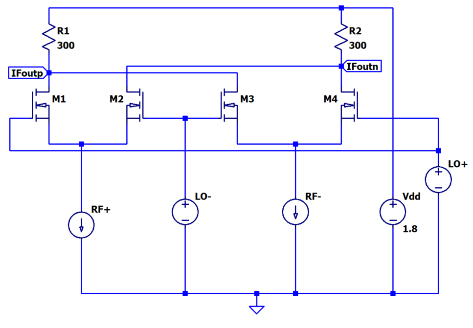
Double Balanced Mixer or Gilbert Cell
Double Balanced Mixers are mainly used to avoid the LO product terms from the output signal. This configuration requires two single-balanced mixer circuits with two differential RF transistors which are connected in parallel and provides an anti-parallel switching pair. The LO product terms are canceled out and RF signal is doubled at the output signal. This configuration produces a high degree of isolation between LO and IF which eases the filtering requirements used after mixing the signal. For noise, these mixers are less susceptible than the single-balanced mixers because of its differential RF signal. This mixer is also known as the Gilbert Cell.
Figure 9. Gilbert Cell Configuration
As observed in the circuit, there is a lot of symmetry of the Gilbert cell mixer. This enables the balance to be obtained and the rejection of the LO and RF signals at the output. The Gilbert cell is not as widely used within systems using discrete components because of the number of components required is high. However, for integrated circuits Gilbert cell mixers are ideal because the number of components is not particularly important, they do not require wound components like transformers or other inductors and they are able to offer a high level of performance.
LTSpice Simulation
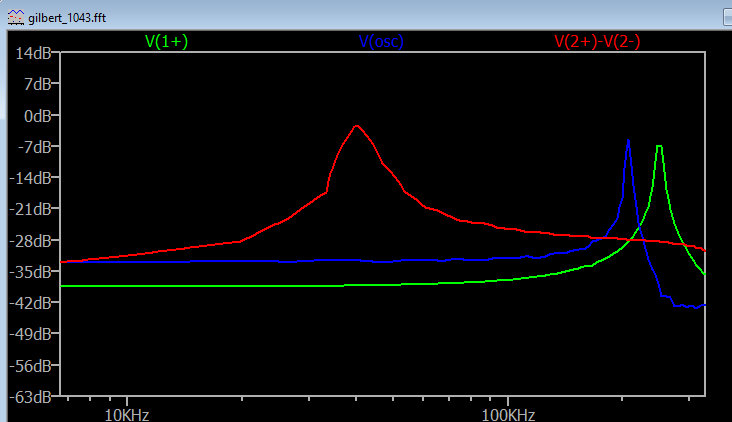
Since the component provided in the kit is not enough to construct the circuit, let’s instead simulate the circuit in LTspice. See Lab Resources to download the LTspice files for simulation. Seen in Figure 10 is the IF output of the circuit. We took the difference between the positive and negative IF output.
Figure 10. Gilbert Cell LTSpice Simulation
Double balanced active mixer implemented with LTC1043
The double balanced mixer configuration requires two single-balanced circuits. We can build this configuration with LTC1043 as it has many swithches and it provides the anti-paralell switching pair needed. In Figure 11 is presented the schematic of the circuit. The circuit and the connections are almost the same, only the inputs of the second switch(S3A S4A) are connected in reverse order to the inputs of the first switch (S1A S2A). In this case, the output is visualized with oscilloscope channel 2+ at pin Ca+ and 2- at pin Ca-.
Figure 11. Double balanced mixer with LTC1043
To analyze the Down-conversion configuration on channel 1 of the signal generator is generated a sinewave with 250kHz frequency and 1V amplitude peak-to-peak. In Figure 12 is presented the resulting FFT analysis.
Figure 12. Down-conversion FFT analysis
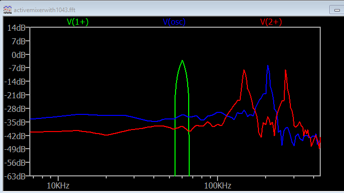
For Up-conversion the sinewave generated on channel 1 will have a frequency smaller than that of the LTC1043 internal oscillator, for example, 50kHz. The FFT analysis for this frequency value is seen in Figure 13.
Figure 13. Up-conversion FFT analysis
Lab Resources:
Further Readings
Some additional resources:
Return to Lab Activity Table of Contents
Page Tools
Some cookies are required for secure log-ins but others are optional for functional activities. Our data collection is used to improve our products and services. We recommend you accept our cookies to ensure you’re receiving the best performance and functionality our site can provide. For additional information you may view the cookie details. Read more about our privacy policy.
The cookies we use can be categorized as follows:
Strictly Necessary Cookies: These are cookies that are required for the operation of analog.com or specific functionality offered. They either serve the sole purpose of carrying out network transmissions or are strictly necessary to provide an online service explicitly requested by you. Analytics/Performance Cookies: These cookies allow us to carry out web analytics or other forms of audience measuring such as recognizing and counting the number of visitors and seeing how visitors move around our website. This helps us to improve the way the website works, for example, by ensuring that users are easily finding what they are looking for. Functionality Cookies: These cookies are used to recognize you when you return to our website. This enables us to personalize our content for you, greet you by name and remember your preferences (for example, your choice of language or region). Loss of the information in these cookies may make our services less functional, but would not prevent the website from working. Targeting/Profiling Cookies: These cookies record your visit to our website and/or your use of the services, the pages you have visited and the links you have followed. We will use this information to make the website and the advertising displayed on it more relevant to your interests. We may also share this information with third parties for this purpose. Decline cookies
